Summary
This case study describes a turnkey controls project that was executed to upgrade the entirety of a plant distributed control system (DCS). The project was implemented at a power plant in Cincinnati, OH that exports power and steam to several adjacent industrial facilities.
Project Objectives
The plant decided to upgrade the controls for the package Boilers along with the main plant DCS for achieving the following four primary objectives.
- Operability and maintainability: Implement a single plant-wide control platform so that operators and technicians do not have to deal with multiple control systems with different hardware and HMIs.
- Reliability and availability: Ensure that the selected processor and I/O hardware upgrade has a proven track record across various process control application over a wide range industries.
- Code compliance: Ensure that the control panel along with associated logic and HMI programming was designed in conformance with the latest NFPA 85 requirements.
- Fully automated controls: Build the system so each package boiler can be started with a single push-button and with minimum operator intervention.
Project Scope
As part of the project, two single burner boilers (Package Boiler#1 & Package Boiler#2) controls were upgraded. These two boilers supply the steam during increased steam demand, or when the main boiler is not available due to shutdown or maintenance:
- Package Boiler #1 has a capacity of 200,000 lb/hr @650 psig
- Package Boiler #2 has a capacity of 150,000 lb/hr @150 psig
The overall project scope included controls for the two package boilers as well as for the following equipment:
- Main boiler (Boiler #4) – 4 Burner Gas fired, 350,000lb/hr @650 psig
- 10 MW steam turbine generator
- Water treatment plant comprising of reverse osmosis (RO) units and mixed bed polishers
- The balance of plant equipment, comprising a de-aerator, cooling water system, boiler feed water, condensate, instrument air, and other misc. systems
- Plant load shedding controls
Our team was responsible for project management, design and engineering, procurement of hardware/software, and installation and startup. (Installation was sub-contracted to a local electrical contractor.)
Project Details
The demolition of existing hardware and re-wiring was completed in Week 1; startup, checkout, testing, and commissioning were completed in the Week 2.
Total duration of the outage for each package boiler was less than 10 days. The controls for each package boiler included new Burner Management System (BMS) and Combustion Control System (CCS) cabinets (see Figures 1 and 2).

The new BMS design (logic, hardware, and field devices) was in full conformance with the latest NFPA 850 standard.
Redundant field instrumentation was utilized on all critical control loops to increase the reliability and availability of the boilers. As part of this upgrade, Package Boiler #2 was retrofitted with a new burner front so that oil can be used as a fuel in addition to existing gas firing capability. Steam injection was also added as part of fuel oil firing for NOx controls.
For BMS & CCS control cabinets, a single non-redundant control processor was used with required I/O modules. Both cabinets were pre-wired and tested in the shop prior to shipping to the site. The CCS cabinet was also fitted with an HMI for local control.
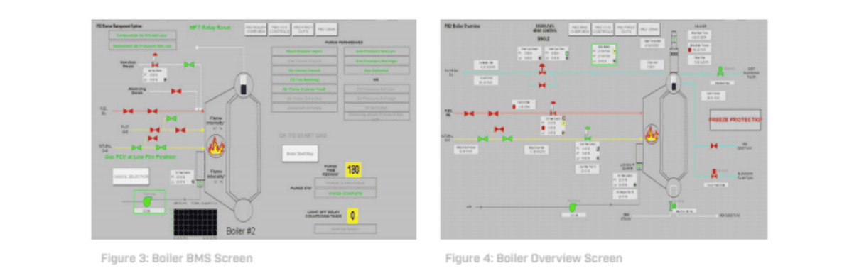
The logic and graphics were programmed to automate the majority of the control functions with minimum operator involvement. (See Figure 3 for typical BMS graphics screen and Figure 4 for boiler overview screen).
Boiler startup is fully automated with a single push-button start (less involvement of the control operator, efficient operation, and complete protection).
This single push-button start performs the following sequence of control actions:
- Start the forced draft (FD) fan, if not running already
- Increase the air flow to purge rate (70% of rated air flow for single burner boiler)
- Purge the boiler for required purge duration (3 to 5 minutes)
- Reduce the air flow after purge sufficient enough for light-off
- Initiate ignition for pilot light-off
- Main burner light-off after pilot flame is proven (i.e., gas or oil depending on fuel selection)
After the 3 minutes of main burner flame is proven, the fuel gas control valve is released for modulation through CCS for firing rate control. CCS controls comprised the following critical control loops with manual auto functions.
- Drum level control
- Fuel flow control
- Air flow control
- O2 trim
- Boiler master, for main steam header pressure control
With all the control loops in auto mode, the boiler is finally placed into auto mode. The controls automatically respond (firing rate control as well as air flow controls with O2 trim) to maintain the desired steam pressure. Combustion controls (air fuel ratio, O2 trim) were tuned after startup to optimize combustion and reduce emissions in consultation with the boiler and burner OEMs. Boiler performance and efficiency calculations also were performed as part of the logic programming for display on the graphic screen and to provide plant management Boiler efficiency data.
The high-pressure steam header is maintained at 650 psig which supplies steam to various industrial facilities surrounding the power plant. Package Boiler #1 was also programmed for auto start whenever the main steam header pressure falls below 600 psig.
Lessons Learned
Utilizing the standard off the shelf control hardware, my team was able to design a cost-efficient control system to replace existing relay-based BMS controls and also bring the BMS controls to the same type of control hardware as the rest of the plant. All HMI graphics were designed representing the process flow diagrams so that the operator can easily navigate to the desired control screen. The control operator also was provided with necessary permissive/interlocks windows to help with the startup and troubleshooting of individual equipment.
100% I/O checkout was performed in the shop along with a full boiler BMS and CCS functional testing (Software FAT) utilizing the simple loop-back simulation. Simulated functional testing helped to address and fix any customer concerns during the software FAT, thus resulting in a faster startup/testing and commissioning on site with zero issues related to logic/graphics on site.
Who is Verve Industrial Protection?
With over 25 years of OT expertise, Verve Industrial is an industrial control systems cyber security company. Verve partners with clients to bridge IT OT security challenges in industrial environments.
The Verve Security Center provides robust asset inventory, vulnerability assessment, threat detection and the ability to safely remidiate risks in a unified software-based platform.
Verve Industrial serves industries across utilities (such as power, oil & gas, water), manufacturing, healthcare, and building controls.